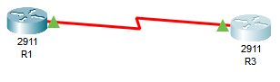
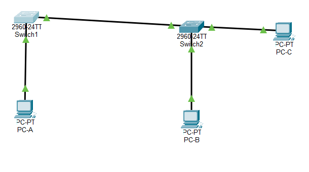
Today I’m working on a simple lab in Packet Tracer to configure VLAN’s shown on the topology below. My source for the information for this lab is the Cisco Networking Academy.
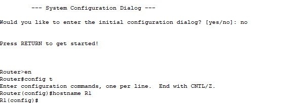
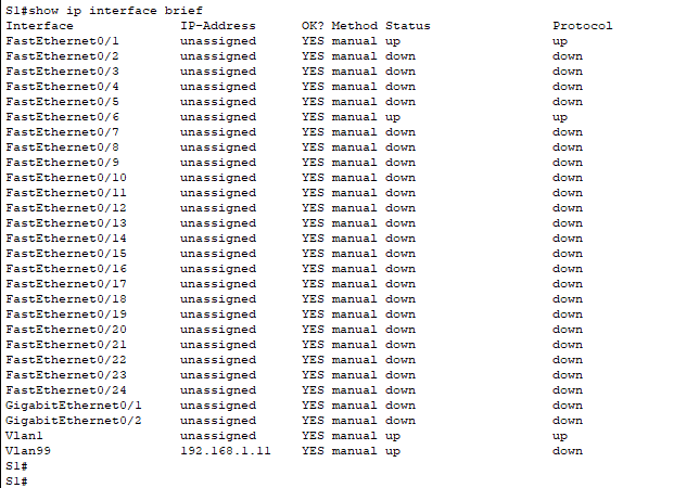
My first step after setting up the switches and cabling, and setting the IP addresses on the PC’s and the default VLAN, was to configure the VLAN settings. First S1:

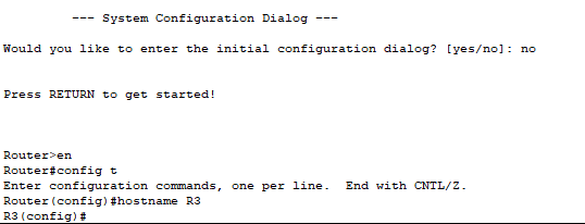
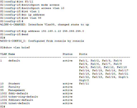
Then S2:

A show VLAN command shows the VLAN’s I’ve set up:

I then moved my Access port for PC-A to VLAN 10 and moved the IP address of the switch to VLAN99:

I then did the same with Switch 2 and PC-B:
I then moved ports f0/11-24 to VLAN 10.
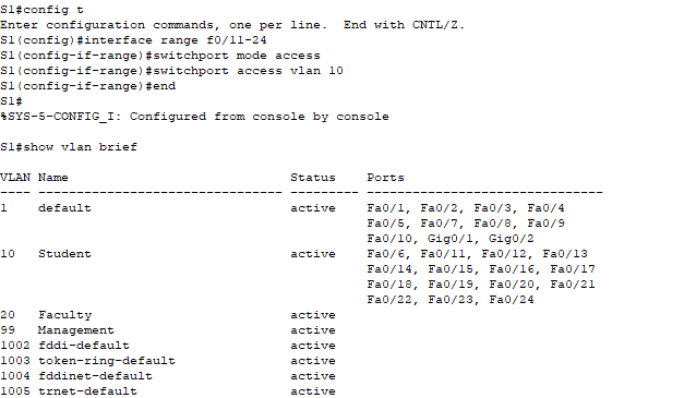
I then moved ports 11 and 21 to VLAN 20

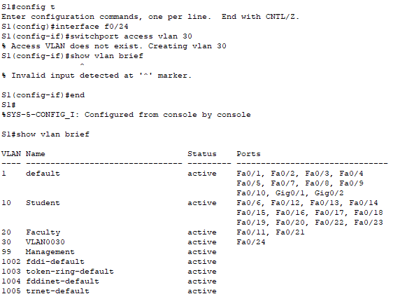
Next I removed port 24 from the current VLAN assignment which moved it back to the default VLAN.

My next step was to move port 24 to VLAN 30 which automatically created VLAN 30 since it did not previously exist.
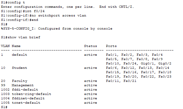
Next I removed VLAN 30. After doing this port 24 was no longer assigned to any VLAN which would mean it would not pass any traffic.

So I ran the following command to reassign it to the default VLAN:
My next step was to set up Dyanmic Trunking Protocol between the two switches.

The show vlan brief command indicates that port f0/1 is no longer in the VLAN database because it is now a trunk port.

The show interfaces trunk command shows that we have trunking established between the two switches. f0/1 on S1 is set to desirable and f0/1 on S2 is set to auto.


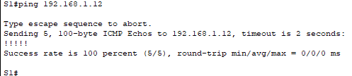
I can verify that traffic is passing over the trunk because S1 can ping S2.
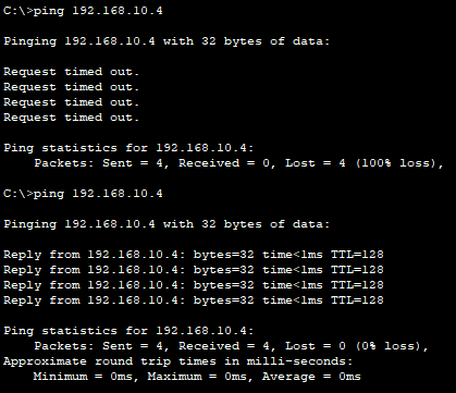
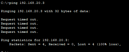
PC-A can now ping PC-B because they are in the same VLAN. However, PC-A cannot ping PC-C because they are in different VLAN’s.
Next I manually configured trunking for f0/1 on both switches.


There may be certain scenarios where manually assigning trunking can be benefitial as not all equippment supports DTP.
I hope you enjoyed this blog post. Thanks for reading!